I'm currently majoring in mechanical engineering at Montana State University and am on track to graduate with a bachelor's of science in 2025. I also plan on obtaining a minor in aerospace engineering during this time. After I graduate I plan on going into the mechanical engineering masters program at MSU as well.
I'm also a dedicated member of Montana State's men's Track & Field team, and am very proud to represent bobcat athletics.
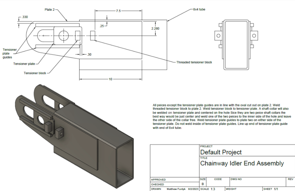
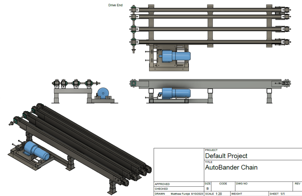
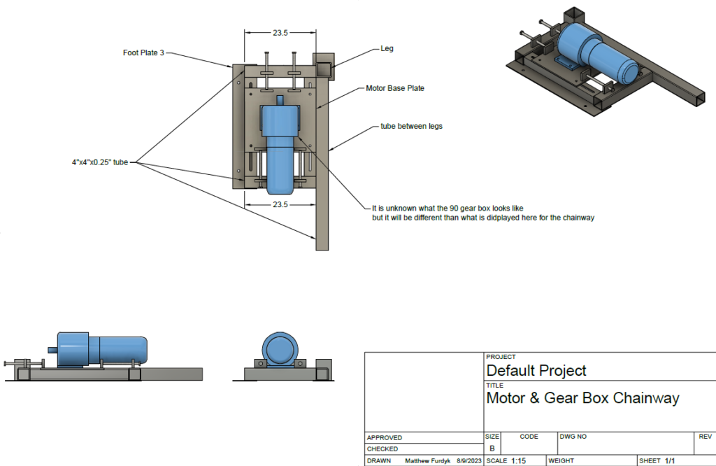
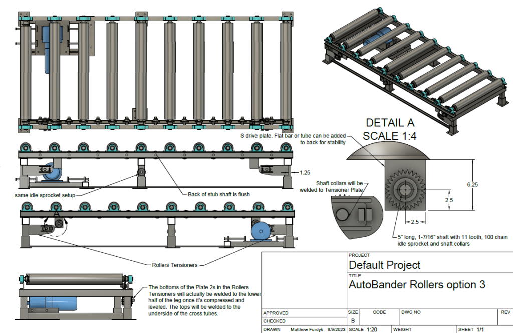
The goal for this project design was to fully design a motor driven roller system and motor driven chainway system from scratch for an automatic wood load bander. As well as making all necessary/desired parts serviceable. Other restraints include dimensional constraints, motor placement, and system operation speed.
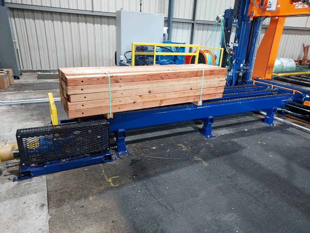
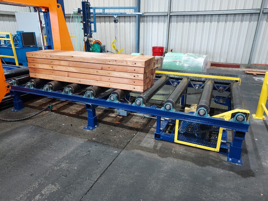
The first part of this project was designing the frames for the roller and chainway systems. Which needed to be adjustable upon installation and meet height requirements. This was achieved by making the legs out of different sized tubing so that each system could be lowered and leveled to match the auto banding machine. The second part was designing the actual chainways and roller systems while being able to tension all drive chains. The rollers were driven by a chain and gear system on the side and had tensioners attached to the frame legs. The motor, and tensioning frame it sits on, was then placed under the rollers and on the bottom of the chain system. This simple design allows all damaged bearings, gears, rollers, chains and tensioners to be replaced. The chainways were designed with an idler end that had a bolt and nut system capable of tensioning each chain individually. While the other end had a common, keyed drive saft. The motor and it’s tensioning frame also attach to this drive shaft. But because the chainway system’s limited undercarriage space, the motor had to be installed outside of the system. This design allows all shafts, keys, gears, and tensioners to be replaced if damaged. After installation and operation testing, safety guards were installed for operators.
This project allowed me to apply my knowledge and skills such as professional communication, 3D modelling, machine design, teamwork through design process, and system dynamics to a hands-on problem. Being able to utilize my skills as well as working closely with Steel River allowed us to develop an efficient and highly functional system. This system removed the need for manned positions while greatly improving production efficiency.
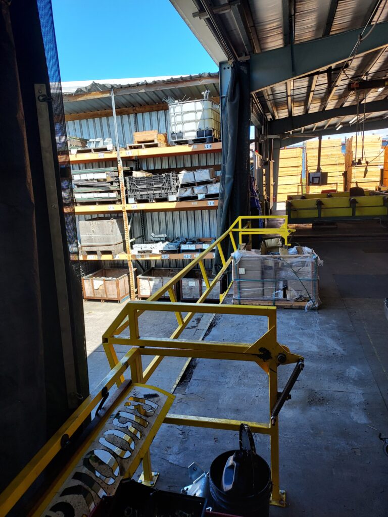
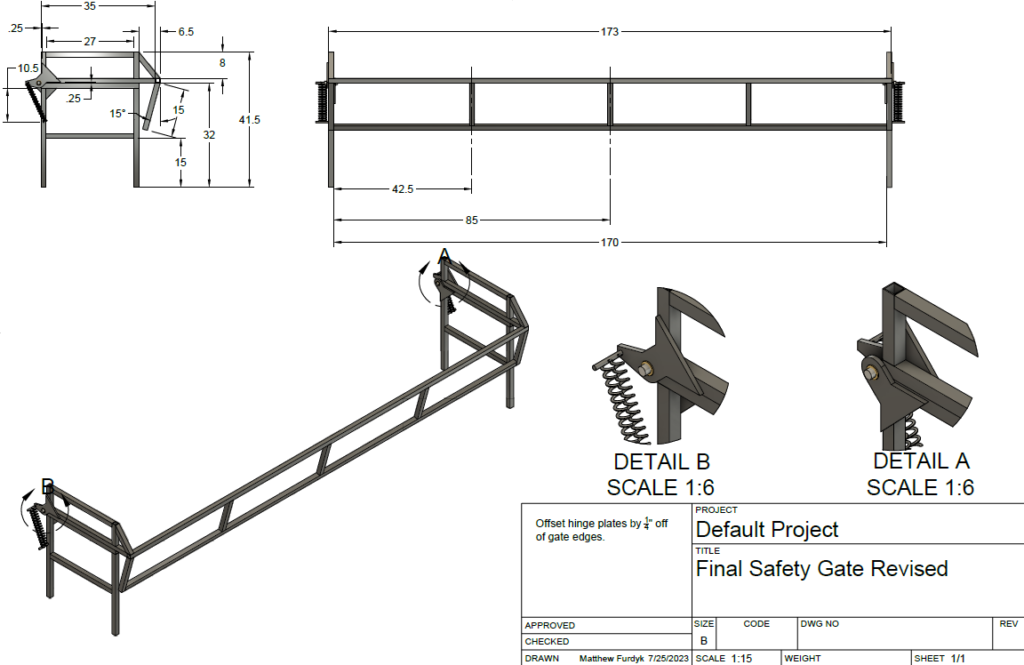
Safety Gate Design Project
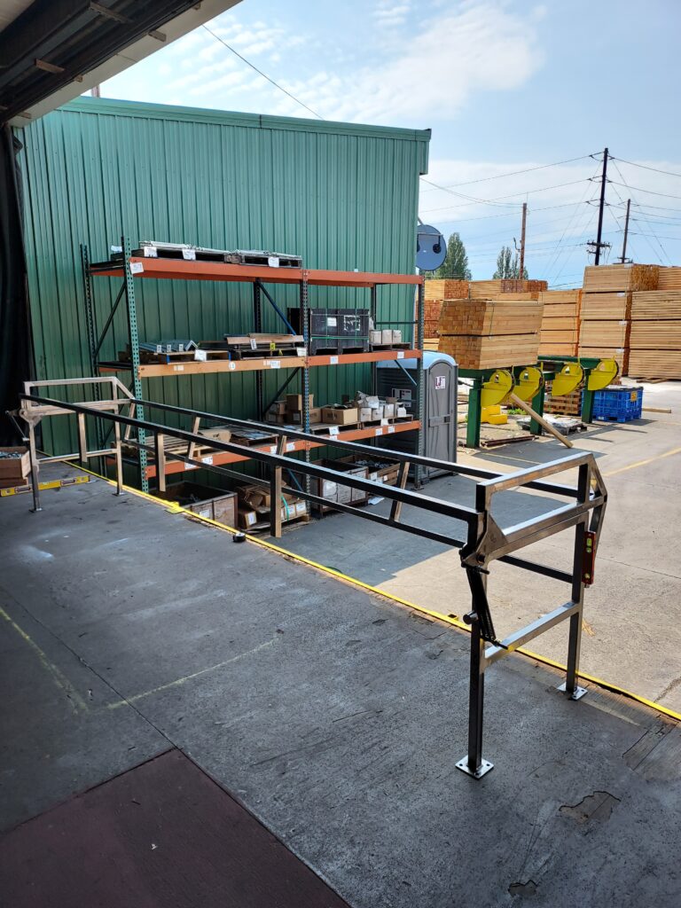
The most important objective for this project was to install a railing/gate for Brooks Manufacturing to keep operators from falling off of a loading bay. Other objectives include installing an intuitive system and working within dimension constraints.
After two months of research and reaching out to both local and international companies that supply like-product, it became apparent that this project would have to be built from scratch. Several designs and functions had been presented to me from mentors and managers that had to be included. From the research and information acquired I designed a fold-over spring assisted gate. The only of it’s kind in the United States as far as capacity and functionality. This prototype design allowed there to be a technical railing whether it’s open or closed and allowed 3-4 pallets of product to be loaded on the bay at a single time. As well as using no more than 3 feet of loading bay space and meeting OSHA regulations. After going through the design process with my mentors, I performed necessary dynamics and stress calculations for the spring system, bushings, and plate joinery. Then we worked closely with Steel River to install our finalized design.
This project allowed me to apply my knowledge and skills such as professional communication, 3D Modelling, mechanics of materials, teamwork through design process, and system dynamics to a hands-on problem. Being able to apply my skills and working with companies such as Morse Steel and Steel River allowed us to install a viable and safe solution that is still in operation today.
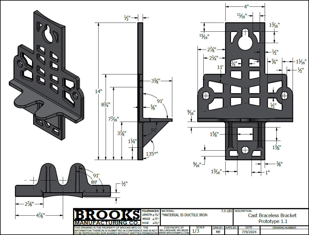
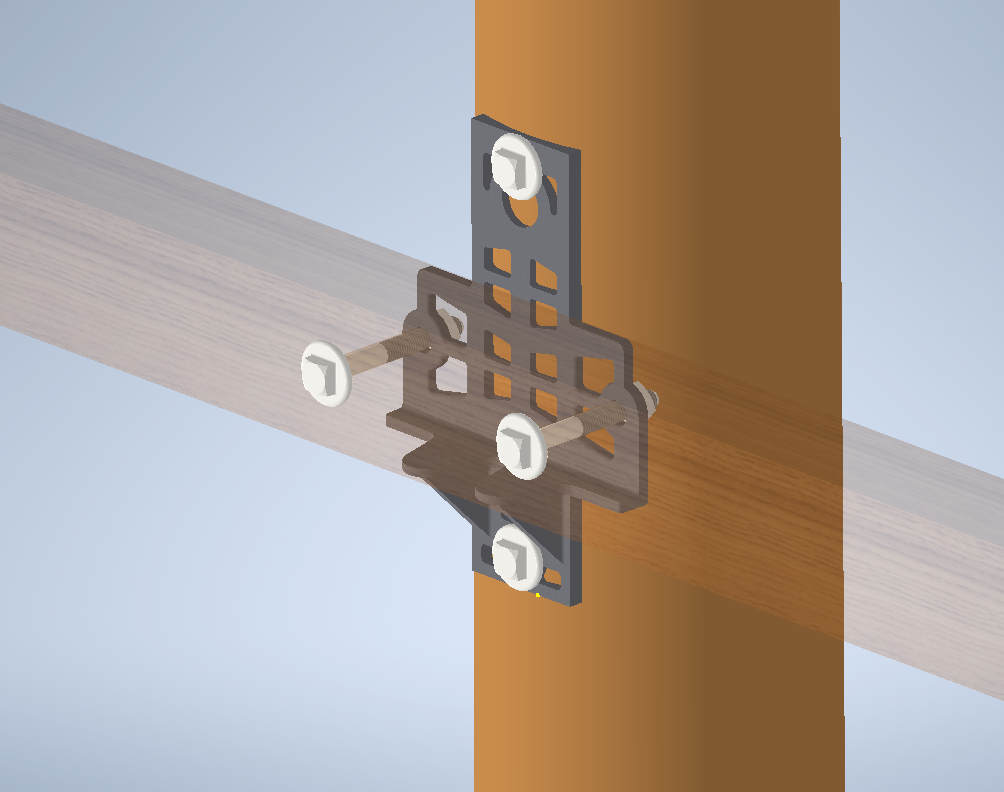
Braceless Bracket Redesign Project
The desired objective for this project was to design a cast version of a current folded sheet metal bracket that was cheaper, easier to manufacture, and similar in strength and weight that Brooks Manufacturing could start marketing/producing.
After analyzing a previous solid cast prototype and making necessary calculations I was able to remove 59.2% of the total material. This placed the prototypes weight within a pound of it’s sheet metal counterpart. All while maintaining it’s structural integrity with high strength rib supports and reducing stress concentrations on edges. These improvements resulted in a maximum stress of 26ksi and a safety factor of 1.53. This part was also designed for face-down ease when casting. It’s two-plane design and drafted faces make it easily extractable.
This project allowed me to apply my knowledge and skills such as cast design, 3D Modelling, mechanics of materials, and system dynamics to a hands-on problem. I was also able to learn quite a bit about Autodesk Finite Element Analysis through my testing. Working with my mentor through the design process and companies such as Tengco and Buyken allowed us to present a viable solution that will soon be in production.
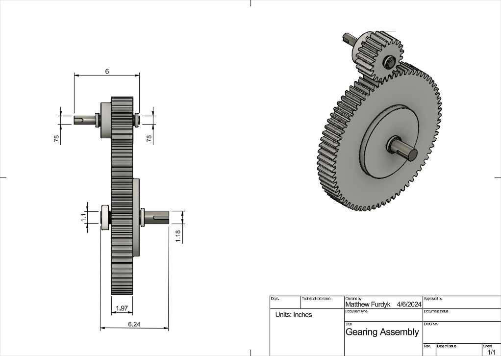
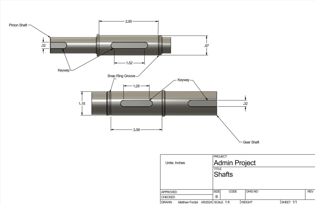
The goal of this project was to design a working shaft and gear system for a band saw. Given operating conditions for the bandsaw, motor input, and minimum factors of safety, it was expected that at no point within the given fatigue life would bearings, gears, shafts, or keyways fail.
The first step of this project was designing reliable stepped shafts for the given torque and reduce as much material as possible. Using a system of equations, diagrams, and a derivative process, we were able to find the minimum diameter for the shaft portions directly inside the gears. Then based upon the loading scenarios and stress concentrations, other diameters for steps, fillets, and keyway sizes were calculated. After the shafts were finalized, the gearing system was analyzed. The deciding factors for our chosen design were gear ratios, tooth count, pressure angle, and tooth stress based on the loading scenario. The final step in this project was selecting the proper lubricated ball bearings based on the fatigue and loading scenario.
This group allowed me to apply my knowledge and skills such as machine design, 3D Modelling, mechanics of materials, and system dynamics to a real-world scenario. This was a challenging and strenuous task. However, my partner and I worked extremely well together on this project and displayed excellent time management skills. My specific role in this project was bearing analysis and selection, stress concentration calculations, gear and shaft equation setup and assistance, and 3D modeling.
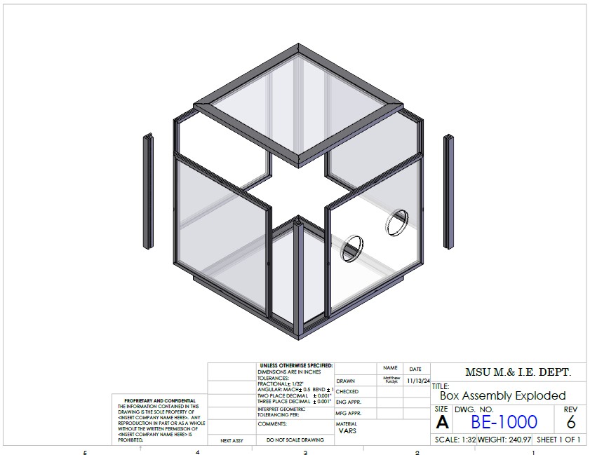
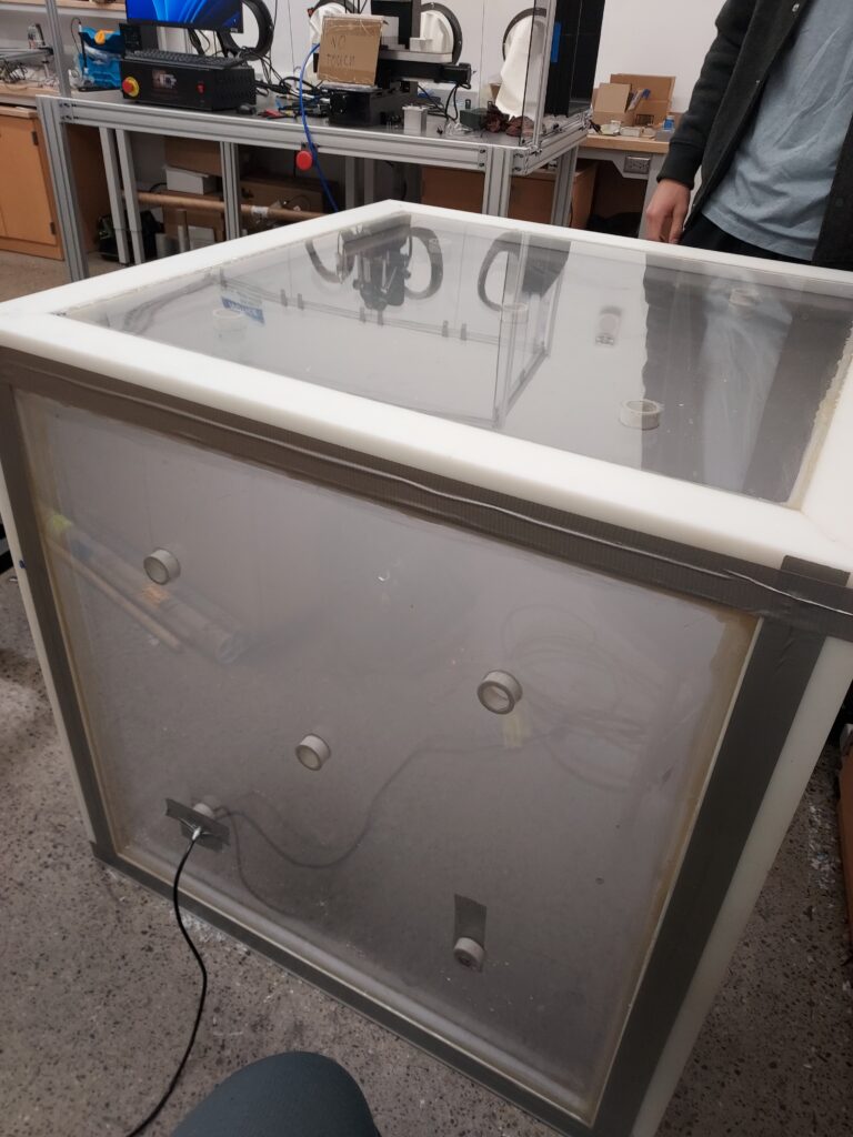
Naval Nuclear Laboratories presented us with the opportunity to develop a modular radiation particulate containment system. This was to be completed with a group of 4-5 engineers from similar disciplines using professional design and manufacturing processes. We were given initial dimensional constraints, budget constraints, time constraints, and objectives to complete. The main objectives were the modular requirement, constructable by a team of 4 within 10 hours, and airtight.
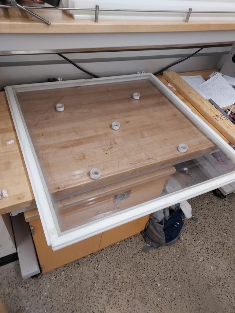
Our team developed a series of tongue and groove interlocking panels that were free of any hardware or fasteners and offered airtight connections. After manufacturing and construction was complete, we performed and passed an airtight smoke test.
This project really helped develop my communication and team prototyping skills. As well as 3D modeling, hands on manufacturing, and intricate/advanced machining processes. After review I would have used a better epoxy and jig system. My specific role within this team was 3D modeling, jig construction, panel machining, panel construction, system assembly, and system testing.
Contact Me
(360)-961-5481
mfurdyk59@gmail.com
1811 S Rouse Ave, Bozeman, MT 59715
I typically reply to all email inquiries within 48 hours.